Market Insights
Author: A. Patel
The bottom pouring process, also known as the uphill teeming process, involves pouring molten metal from the bottom of a mold via a refractory lined system with a mold flux layer typically covering the rising metal front. Bottom pouring is generally considered to provide better surface quality and cleaner material than top pouring. However, some problems linked to this process include freeze offs, surface and internal quality issues due to the presence of entrapped mold flux, reoxidation, and refractory erosion. The fluid flow pattern has been found to be closely associated with some of these problems.
Obtaining insights into metal flow and solidification behavior may improve our understanding of these defects and offer opportunities to reduce them. Computational fluid dynamics (CFD) allows metallurgists to virtually approximate molten metal flow behavior, which otherwise would be difficult considering the high metal temperatures involved and the opaque nature of metal and mold structures. Research and Development modelers at Carpenter Technology employ in-house CFD tools to understand the bottom pouring process.
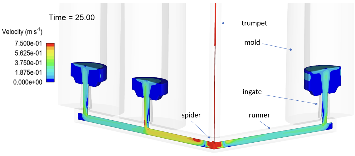
The important process parameters that govern fluid flow are pouring rate, metal temperature, and trumpet-spider-runner-gate design. Figure 1 provides a snapshot of moving molten metal as it travels through trumpet -> spider -> runners -> ingates -> mold. For the mold set up shown below, the model predicted that one mold received slightly more metal than the other two molds in the first 25 s of teeming.
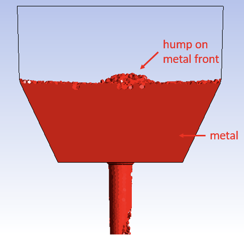
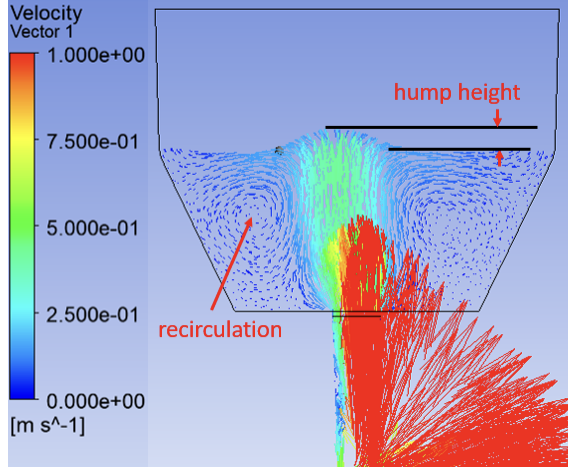
The model also predicted that during the initial stages of teeming, momentum in the vertical direction from the incoming jet was high enough to create a hump in the metal front, as shown in Figure 2. Larger fluctuations in hump height2 and high horizontal velocity may lead to slag entrainment problems. In a worst-case scenario, the high horizontal speed of metal can drag mold powder to the sides, creating a bare surface or “eye”, exposing metal to air. If the mold flux bag is placed too low, the higher horizontal component of velocity and higher level-fluctuations could increase slag entrainment and thereby deteriorate metal cleanliness.
 |
 |
| (a) | (b) |
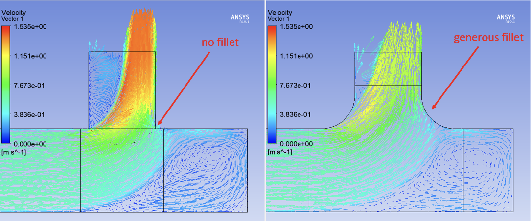
The effect of runner-ingate design on the metal delivery into the mold is presented in Figure 3. The model predicted that a smoother transition at the runner-ingate junction through incorporation of a fillet reduces the flow separation and delivers metal in the mold at a lower velocity. Lower initial velocity reduces the chances of the initial jet splash rising upwards towards the mold bag, falling under gravity, and creating slag entrainment.
| (a) | (b) |
At Carpenter Technology, CFD modeling gives us a better fundamental understanding of flow conditions created by a mold setup — enabling the metals processing team to make continuous improvements and serving as a guide for making parametric assessments before plant-scale trials.

References:
L. Zhang and B. Thomas, State of the Art in the Control of Inclusions during Steel Ingot Casting, Metallurgical and Materials Transactions B, Vol. 37B, 2006, pp. 733-761.
Z. Tan, M. Ersson, and P. Jӧnsson, Modeling of Initial Mold Filling with Utilization of Swirl Blades, ISIJ International, Vol. 52, No. 6, 2012, pp. 1066-1071.