Emerging Technology
Authors: W. Roth, K. Stritch
Rising Step Load (RSL) Testing
Carpenter Technology offers high-performance alloys for a variety of harsh environments across the industrial, medical, and aerospace markets. Environmentally assisted cracking (EAC) is a pernicious form of failure onset by the synergy between mechanical loading, corrosive environment, and susceptible materials. EAC is often not identified in service until complete failure, so characterizing a material's resistance to EAC is crucial to providing successful material solutions in demanding applications. Carpenter Technology leverages rising step load (RSL) testing to determine the EAC resistance of many of our high-strength, high-toughness materials, such as Custom 465®.
For nearly a decade, our research and development team has been using the RSL system to determine critical fracture toughness parameters such as the critical stress intensity of EAC (). Additionally, RSL testing can determine traditional fracture toughness ( and the critical stress intensity of hydrogen embrittlement (). These values are calculated and validated in accordance with ASTM E399, ASTM F1624, and ISO 7539-6.
One of the main benefits of RSL testing with the four-point bend setup is the use of single-edge notch (SEN) bend specimens (ASTM E1290). These are equivalent to standard Charpy specimens for impact testing, and therefore require a smaller amount of material for evaluation and a lower amount of machining preparation. Additionally, RSL tests can be completed in days, rather than the weeks necessary for prior test standards such as double cantilever beam (DCB) specimens.
How RSL Testing Works
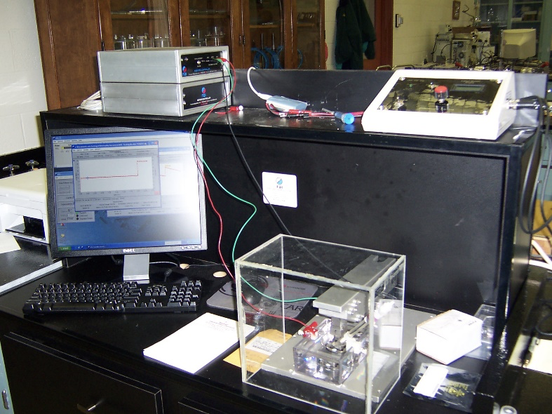
While there are many different loading and setups for RSL testing, the specific instrument used by our R&D team is a four-point bend cantilever frame bordered by a plexiglass test chamber that allows for environmental testing of various solutions and potentials (Figure 1).
The general setup for RSL testing involves fatigue pre-cracking of the sample, preparation of the test environment and then preparing the load profile. Once setup, the test is conducted. Following material failure, the fracture surface is then analyzed, and the test is validated with the ASTM standards referenced above. The following section will discuss these procedures in a little more detail.
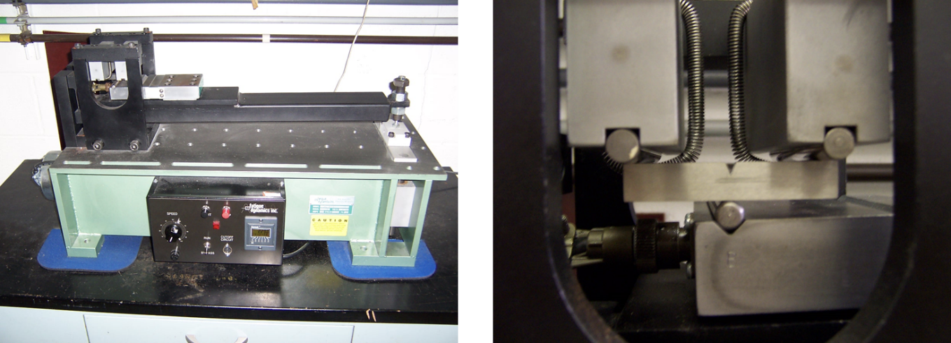
To fatigue pre-crack the machined Charpy specimen, the sample is loaded into a three-point bending machine in ambient air. Care must be taken to ensure that the fatigue pre-crack results in a small, localized plastic zone ahead of the crack tip so that linear elastic fracture mechanics (LEFM) can be applied in the calculations of test validity.
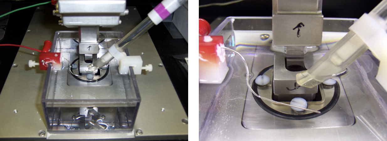
After the sample is pre-cracked, the sample is cleaned and loaded into the four-point bend apparatus. An environmental solution is then introduced into the test reservoir. The test can be set up to occur at open circuit potential (OCP) or at an applied potential. For example, a test potential can be held at -1.12 to simulate the cathodic coupling to zinc in an aqueous environment. In the case of a dynamic environment, OCP can be maintained to simulate the fluctuation of material passivity and environmental chemistry. The versatility of the RSL system allows for specific replication of end-use environments in a controlled laboratory setting to best evaluate material performance.
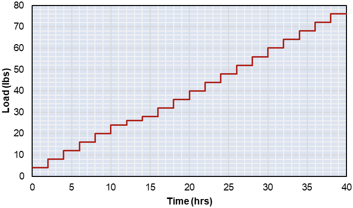
Once the material is loaded and the environment established, testing begins. The material is step-loaded and held at constant load at a user-specified ramp rate. These profiles are typically derived from load profiles in ASTM F1624. For example, at a 20/5/4 load profile, there would be 20 steps at increases of 5% of the target load for 4-hour holds at each step (Figure 4).
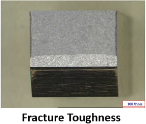
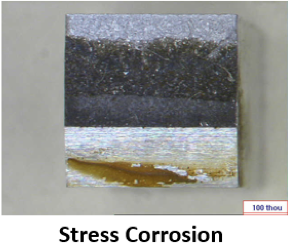
The material will often fail prior to the completion of a given load profile. The maximum load until failure is recorded, and the fracture surface is analyzed for test validity. The ease of sample preparation and quick test duration allows a multitude of samples to be prepared for a given material, providing improved sample statistics rather than reliance on a single datapoint for determination. An example of fractured RSL tests is shown in Figure 5.
 |
 |
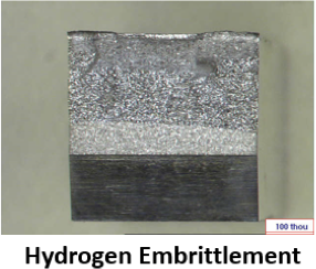 |
Fracture surface analysis often continues under a scanning electron microscope (SEM) to classify the type of failure, whether it is ductile dimpling, transgranular (TG), intergranular (IG), or a quasi-cleavage mixed mode failure. Understanding the fracture surface is vital to understanding the deformation modes and EAC susceptibility of materials. This understanding best ensures that the proper material, heat treatment, and/or processing route is selected for the demanding applications where the materials will be employed.
The Carpenter Technology team relies extensively on RSL testing to characterize the EAC resistance of many of our alloys. Whether high-strength Custom 465 for aerospace structural components or Ti 6Al-4V for medical implants, RSL testing provides ease of sample preparation and a level of testing efficiency that allows for rapid, accurate results — generating improved sample statistics over previous test methods.